Light: Definition
Light is a form of energy that enables us to see things. Light starts from a source and bounces off objects which are perceived by our eyes, and our brain processes this signal, which eventually enables us to see. Maxwell predicted that magnetic and electric fields travel in the form of waves, and these waves move at the speed of light. This led Maxwell to predict that light itself was carried by electromagnetic waves, which means that light is a form of electromagnetic radiation.
How do we see objects?
Our eyes alone do not allow us to see. Light from a source falls on an object and then bounces off onto our eyes and that is how we perceive it.
Nature of Light
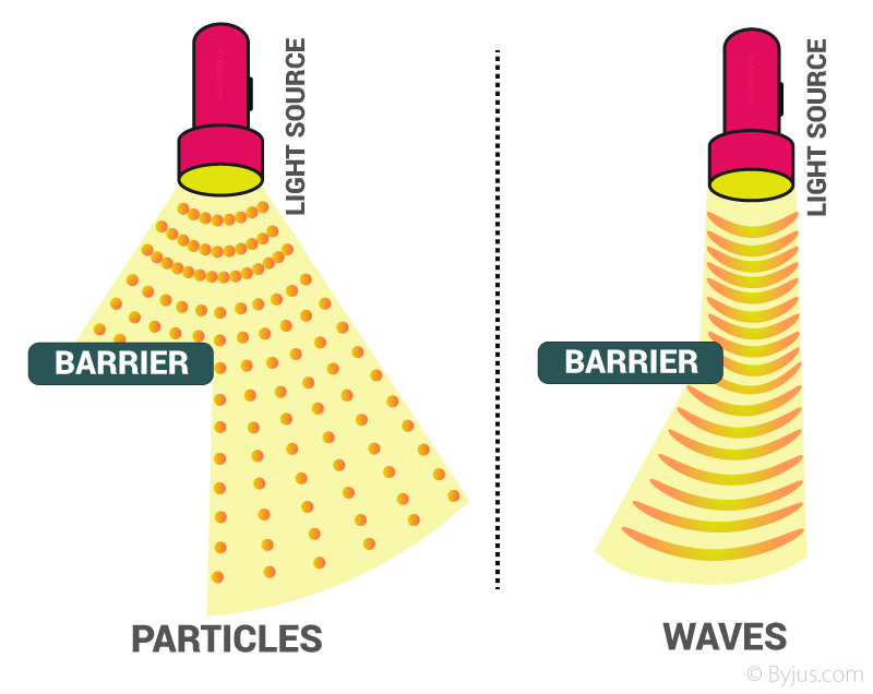
Light behaves as a:
- ray, e.g. reflection
- wave, e.g. interference and diffraction
- particle, e.g. photoelectric effect

According to the concept of wave-particle duality in quantum mechanics, light exhibits both particle and wave nature, depending upon the circumstances. A phenomenon like diffraction, polarisation and interference could be explained by considering light as a wave. A phenomenon like the photoelectric effect is explained by assuming that light consists of particles called photons.
Laws of Reflection
Light Incident on the Surface Separating Two Media
When light travels from one medium to another medium it either:
- gets absorbed (absorption)
- bounces back (reflection)
- passes through or bends (refraction)
When light is incident on a plane mirror, most of it gets reflected, and some of it gets absorbed in the medium.

Characteristics of Light
- The speed of light is given as c=λμ, where λ is its wavelength and μ is its frequency.
- The speed of light is a constant which is 2.998×10⁸m/s or approximately 3.0×10⁸m/s.
Reflection of Light by Other Media
A medium that is polished well without any irregularities on its surface will cause regular reflection of light. For example, a plane mirror. But even then, some light gets absorbed by the surface.
Laws of Reflection
The incident ray, reflected ray and the normal all lie in the same plane. Angle of incidence = Angle of reflection
[∠i=∠r]

Propagation of Light
Rectilinear propagation of light: Light travels in a straight line between any two points.

Fermat’s Principle
- The principle of least time: Light always takes the quickest path between any two points (which may not be the shortest path).
- Rectilinear propagation of light and the law of reflection [∠i=∠r] can be validated by Fermat’s principle of least time.
Applications of Fermat’s Principle
We can make several observations as a result of Fermat’s Principle, which will prove useful as we explore the realm of geometric optics:
- In a homogeneous medium, light rays are rectilinear. That is, in any medium where the index of refraction is constant, light travels in a straight line.
- The angle of reflection of a surface is equal to the angle of incidence. This is the Law of Reflection.
Example of Fermat’s Principle
Mirage is an example of this phenomenon. Sometimes, we feel like we are seeing water on the road, but when we get there, the road is dry. What we really witness is the light of the sky, which is reflected on the road. Since the air is very hot just above the road, but it is cooler up higher. Hot air expands more than cool air and is thinner, this leads to less decrease in the speed of light.
Plane Mirror
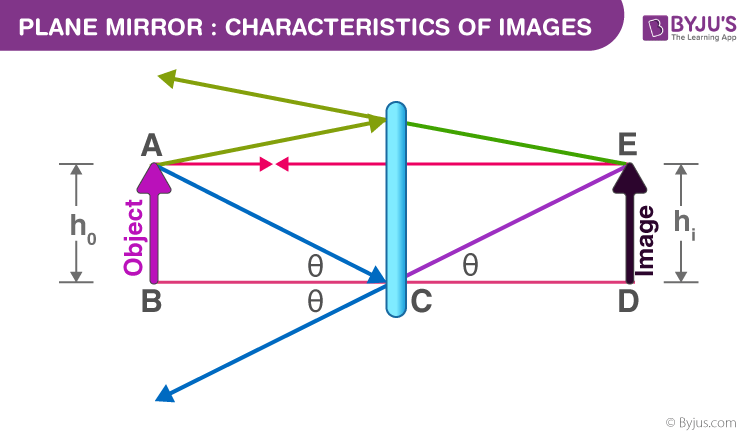
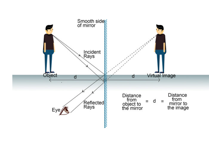
Any flat and polished surface that has almost no irregularities on its surface that reflect light is called a plane mirror.
Image Formation by a Plane Mirror
- The image formed by a plane mirror is always virtual and erect.
- Object and image are equidistant from the mirror.

Characteristics of Images
- Images can be real or virtual, erect or inverted, magnified or diminished. A real image is formed by the actual convergence of light rays. A virtual image is an apparent convergence of diverging light rays.
- If an image formed is upside down, then it is called inverted or else it is an erect image. If the image formed is bigger than the object, then it is called magnified. If the image formed is smaller than the object, then it is diminished.
To know more about Plane Mirror, visit here.
Principle of Reversibility of Light
If the direction of a ray of light is reversed due to reflection off a surface, then it will retrace its path.
Spherical Mirrors
Spherical Mirror
Consider a hollow sphere with a very smooth and polished inside surface and an outer surface with a coating of mercury so that no light can come out. Then if we cut a thin slice out of the shell, we get a curved mirror, which is called a spherical mirror.
Relationship between Focus and Radius of Curvature
Focal length is half the distance between the pole and the radius of curvature.
F = R/2

Curved Mirror
A mirror (or any polished, reflective surface) with a curvature is known as a curved mirror.
Important Terms Related to Spherical Mirror

- Pole (P): The midpoint of a spherical mirror.
- Centre of curvature (C): The centre of the sphere that the spherical mirror was a part of.
- The radius of curvature (r): The distance between the centre of curvature and the spherical mirror. This radius will intersect the mirror at the pole (P).
- Principal Axis: The line passing through the pole and the centre of curvature is the main or principal axis.
- Concave Mirror: A spherical mirror with a reflecting surface that bulges inwards.
- Convex Mirror: A spherical mirror with a reflecting surface that bulges outwards.
- Focus (F): Take a concave mirror. All rays parallel to the principal axis converge at a point between the pole and the centre of curvature. This point is called the focal point or focus.
- Focal length: Distance between pole and focus.
Rules of Ray Diagram for Representation of Images Formed
- A ray passing through the centre of curvature hits the concave spherical mirror and retraces its path.
- Rays parallel to the principal axis passes through the focal point or focus.
Image Formation by Spherical Mirrors
For objects at various positions, the image formed can be found using the ray diagrams for the special two rays. The following table is for a concave mirror.

Uses of SphericalMirror based on the Image Formed
Concave and Convex mirrors are used for many daily purposes.
Example: Rear view mirrors in vehicles, lamps, solar cookers.
Mirror Formula and Magnification
| 1/v + 1/u = 1/f |
where ‘u’ is object distance, ‘v’ is the image distance and ‘f’ is the focal length of the spherical mirror, which is found by the similarity of triangles.
- The magnification produced by a spherical mirror is the ratio of the height of the image to the height of the object. It is usually represented as ‘m’.
Sign Convention for Ray Diagram
Distances measured towards positive x and y axes (coordinate system) are positive, and towards negative, x and y-axes are negative. Keep in mind the origin is the pole (P). Usually, the height of the object is taken as positive as it is above the principal axis, and the height of the image is taken as negative as it is below the principal axis.
Position and Size of Image Formed
The size of the image can be found using the magnification formula m = h’/h = – (v/u). If m is -ve it is a real image and if it is +ve it is a virtual image.
Refraction Through a Glass Slab and Refractive Index
Refraction
The shortest path need not be the quickest path. Since light is always in a hurry, it bends when it enters a different medium as it is still following the quickest path. This phenomenon of light bending in a different medium is called refraction.

Laws of Refraction
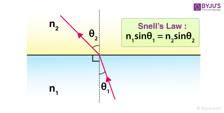
- The incident ray, the refracted ray and the normal to the interface of two transparent media at the point of incidence all lie in the same plane.
- The ratio of the sine of the angle of incidence to the sine of the angle of refraction is a constant for the light of a given colour and for the given pair of media. This law is also known as Snell’s law of refraction.
Absolute and Relative Refractive Index
The refractive index of one medium with respect to another medium is called the relative refractive index. When taken with respect to a vacuum, it’s known as an absolute refractive index.
Refraction through a Rectangular Glass Slab
When the light is incident on a rectangular glass slab, it emerges out parallel to the incident ray and is laterally displaced. It moves from rarer to a denser medium and then again to a rarer medium.
Refraction at a Planar Surface

Following Snell’s Law:
- Light bends towards the normal when moving from rarer to denser medium at the surface of the two media.
- Light bends away from the normal when moving from denser to rarer medium at the surface of contact of the two media.
Refractive Index
The extent to which light bends when moving from one medium to another is called the refractive index. This depends on the ratio of the speeds in the two media. The greater the ratio, the more the bending. It is also the ratio of the sine of the angle of incidence and the sine of the angle of refraction, which is a constant for any given pair of media. It is denoted by:
n = sin∠i/sin∠r = speed of light in medium 1/speed of light in medium2.
The ratio of the speed of light in a vacuum to the speed of monochromatic light in the substance of interest is known as the relative refractive index. Mathematically, it is represented as:
n = c/v
Where n is the refractive index of a medium, c is the velocity of light in a vacuum and v is the velocity of light in that particular medium.
Total Internal Reflection

- When the light goes from a denser to a rarer medium, it bends away from the normal. The angle at which the incident ray causes the refracted ray to go along the surface of the two media parallelly is called the critical angle.
- When the incident angle is greater than the critical angle, it reflects inside the denser medium instead of refracting. This phenomenon is known as Total Internal Reflection.
E.g. mirages, and optical fibres.

Spherical Lens
Refraction at Curved Surfaces
When light is incident on a curved surface and passes through, the laws of refraction still hold true, for example, lenses.
Spherical Lenses
Spherical lenses are lenses formed by binding two spherical transparent surfaces together. Spherical lenses formed by binding two spherical surfaces bulging outward are known as convex lenses while spherical lenses formed by binding two spherical surfaces such that they are curved inward are known as concave lenses.
Important Terms Related to Spherical Lenses
- Pole (P): The midpoint or the symmetric centre of a spherical lens is known as its Optical Centre. It is also called the pole.
- Principal Axis: The line passing through the optical centre and the centre of curvature.
- Paraxial Ray: A ray close to the principal axis and also parallel to it.
- Centre of curvature (C): The centres of the spheres that the spherical lens was a part of. A spherical lens has two centres of curvature.
- Focus (F): It is the point on the axis of a lens to which parallel rays of light converge or from which they appear to diverge after refraction.
- Focal length: Distance between optical centre and focus.
- Concave lens: Diverging lens
- Convex lens: Converging lens
Rules of Ray Diagram for Representation of Images Formed
- A ray of light parallel to the principal axis passes/appears to pass through the focus.
- A ray passing through the optical centre undergoes zero deviation.
Image Formation by Spherical Lenses
The following table shows image formation by a convex lens.

Lens Formula, Magnification and Power of Lens
Lens Formula and Magnification
Lens formula: 1/v = 1/u = 1/f, gives the relationship between the object distance (u), image distance (v), and the focal length (f) of a spherical lens.
Uses of Spherical Lens
Applications such as visual aids: spectacles, binoculars, magnifying lenses, and telescopes.
Power of a Lens
The power of a lens is the reciprocal of its focal length i.e. 1/f (in metre). The SI unit of power of a lens is dioptre (D).


0 Comments